Defining the camera lens
We want to have a way to model how our eyes or a camera sees the world to form a 2D image and apply that to our points. The issue is, that even a very basic camera with a single lens has a lot of effect that are time consuming to represent exactly, like distortion or diffraction effects.
The good news is that we can simplify the model a lot and still get convincing results! The model that we use is called the pinhole camera model and you might even have built the real world version before: A Camera obscura.
Our pinhole model is only different to the camera obscura in that it is for one ideal and on the other hand has the image plane in front of it rather than the back. This way the image is not flipped, which wouldn't be much of a problem, but we would need to handle it.
If we take a sideways view, with the -axis going to the right, the or -axis going up and the image plane being units away from the center, the projection of a pinhole camera can be computed by similar triangles as:
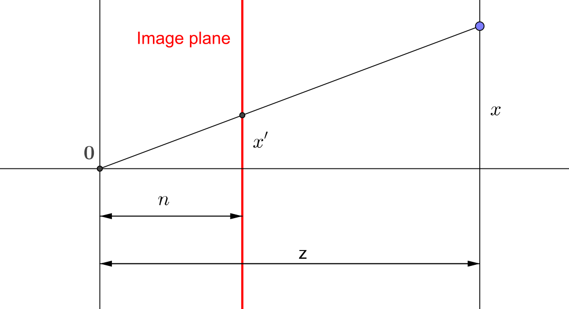
The basic idea now is the following: We already have our vectors with an additional extra dimension, where we put a in for points. How about we construct a matrix that puts the coordinate there instead? Now, this violates our definition, that all points need to have a in th last coordinate. We can easily resolve that by just dividing by the last coordinate, which will then become !
Note: This is actually all part of the so called projective space , where the last coordinate is the homogeneous coordinate.
And this is also equivalent to the formulas above for and .
The simplest matrix to achieve this is the following:
Now this would also remove our current value, which we will be needing as well. The solution is to transform the value as well, so our wanted visible range stays between two values, the near and far plane. We must also negate the values, since by our construction, points outside of the screen, but in the pinhole model it points forward.
There are some additional parts to take care of, but for the rasterization it doesn't actually matter that much, as long as it transforms point according to our requirements. So we won't cover all the details here. If you are interested, this site thoroughly goes through the parts in the matrix that defines our pinhole camera: Songho.
One important note is, that the z-value that we output won't be "linear" anymore. For example, 1 unit along z in the world will take up a different amount of space after the projection depending on whether it is closer or farther away from the camera. This was originally done to make better use of limited precision, giving more precision to points close to the camera and less to points farther away. Today, there are also other ways to handle this, such as reversed z.
A very natural way of parametrizing this kind of projection is by specifying the viewing angle together with the near and far plane. This defines a symmetric frustum, a viewing pyramid. You might know this from stealth games, where you get a visualization of what region an NPC can detect anything.
We can construct the matrix ourselves or use a predefined function:
/**
* Computes a 4x4 perspective matrix given a field of view
*
* Note: This includes a z-coordinate flip
*
* @param {number} fov - The full field of view
* @param {number} aspect - The aspect ratio width/height
* @param {number} near - The near plane
* @param {number} far - The far plane
* @returns {Mat} The perspective matrix
*/
jsm.perspective(fov, aspect, near, far)
// Example
// create a 120 degree perspective matrix for
// the image with aspect ration img.w/img.h
// Set the near and far plane to some arbitrary
// values that fit your scene, here 0.1 and 100
const P = jsm.perspective(
jsm.deg2rad(120), img.w/img.h, 0.1, 100
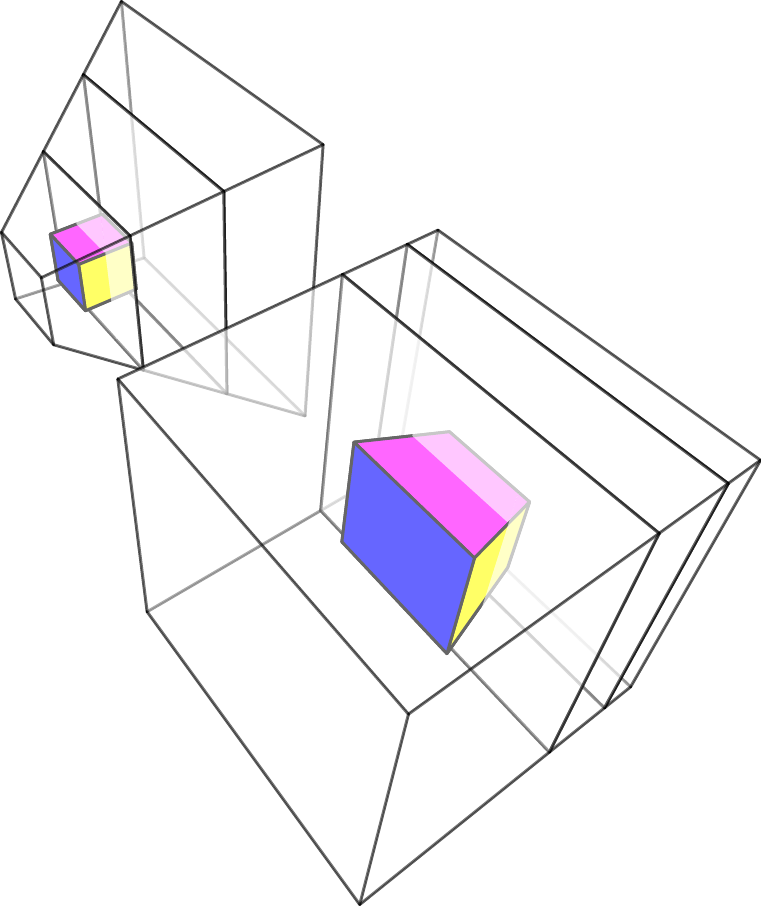
);Importantly, the perspective matrix is designed in such a way, that the visible volume (left to right, bottom to top, near to far) is mapped to the cube in after perspective division (dividing by the last coordinate).
Before this division, we refer to the coordinate system as clip space. After the division, we call it normalized device coordinates or NDC for short.
Now, we can even visualize what happens, when we apply the matrix and the perspective division! How to we get the effect of perspective? Basically, we squish together our viewing frustum into a cube. On the screen, this will then look just like the way line are distorted in perspective. It does look like this: